14, Electronics
Drum switch / pad
(advanced experiment)
There’s so much interesting science in music, for example the study of waveforms, electronics, sociology, mathematics. Music is a scientific playground.
In this experiment you’re going to make a simple electronic drum switch. Even though it’s simple, it uses the bread board and you need to pay attention. You may need help and definitely some patience.
The process
We’re going to do things a little backwards. First we’re going to wire things up and then I’m going to try and explain it all.
You’re going to learn about transistors. The transistor could be the greatest invention in all history. It’s arguably more important than the wheel. Yes really.
This is because the transistor is critical to all computers, mobile phones, digital cameras, watches, you name it. The modern world would not exist without the transistor.
What you’ll need
You will need access to Google and sites like Youtube, Hackster and Instructables.
We’ll use one piezo sensor, some 2mm aluminium sheet, rubber matt and glue to build a basic pad. Once you’ve got this working the sky is the limit, you can even build your own set of electronic drums (however to do that you’ll need to buy something like an Arduino for about $35).
Note: all parts needed to make our switch are in the “Kate Witch Science Set”, except for the can of spray mount.
- 2-3mm thick aluminium disk. 15cm diameter.
- 2-4 mm thick neoprene disk 15cm diameter (old mouse pads are often great for this)
- 4+ mm thick soft foam disk (soft packing foam) in 15cm diameter.
- piezo sensor,
- bread board
- 1ohm resistor
- spray mount or regular craft glue (not included in set).
The circuit
First we’ll wire up the circuit, we’re going to use our breadboard and a few components. You will need:
1 x 2N3904 transistor 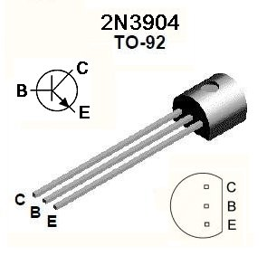
1 x breadboard 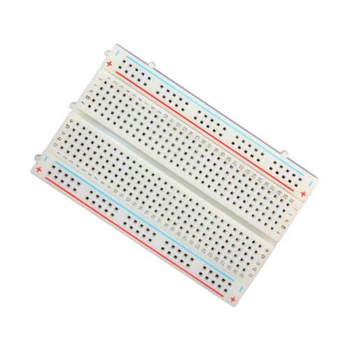
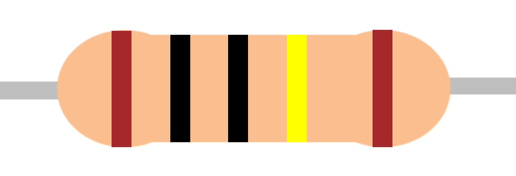
1 x 1 meg resistor. Brown, Black, Black, Yellow, Brown. Note the yellow may look lime green on some resistors.
2 x 47k resistor. Yellow, Violet, Black, Red, Brown.

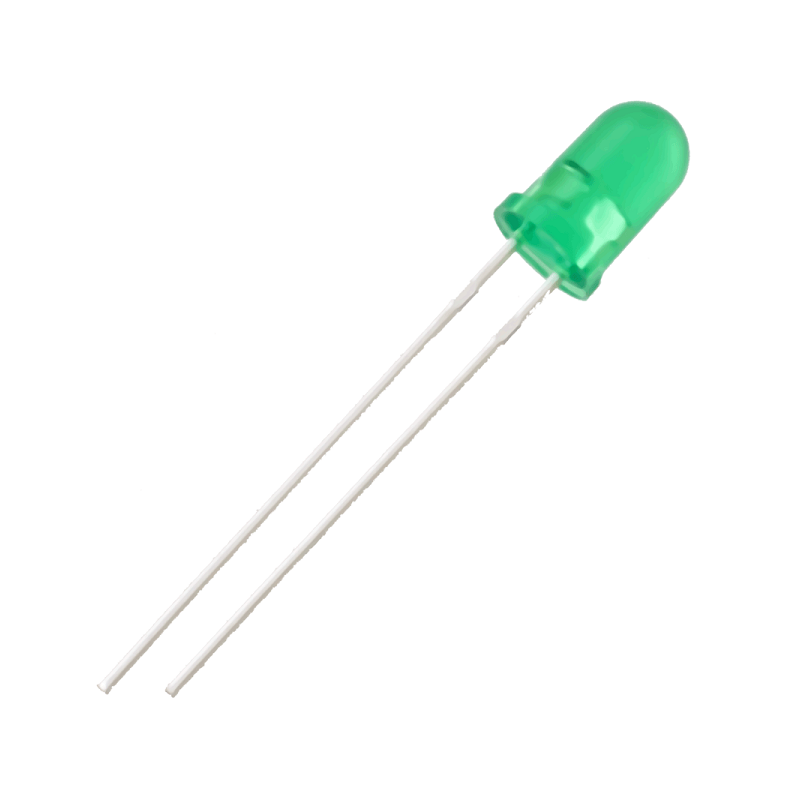
1 x green or red LED. Long leg is positive.
1 x 4 lemon battery. 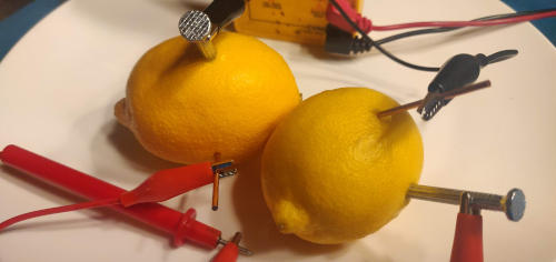 If you don’t have your lemon battery to hand, we can also use the 9v battery needed for the lie detector.
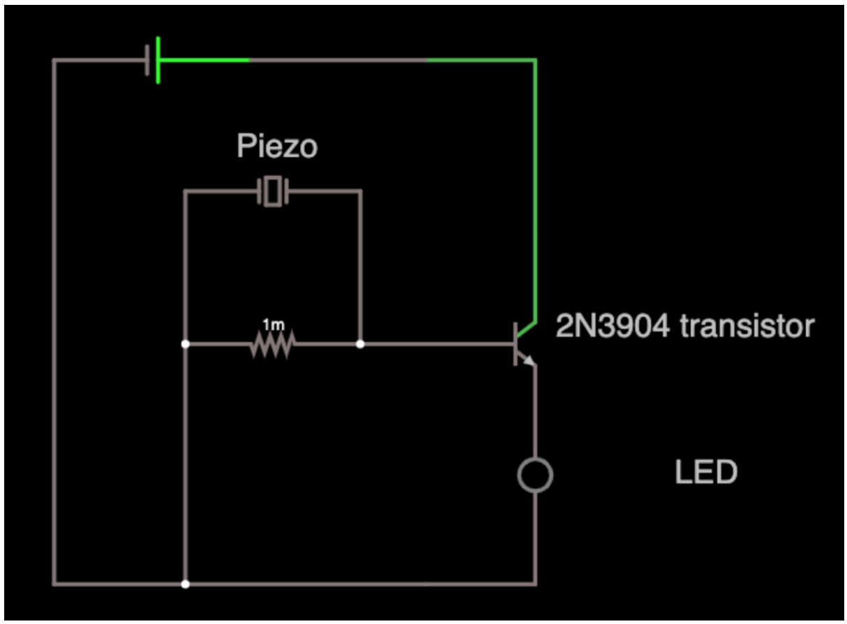
Here is the circuit that you need to wire up if you’re using your lemon battery.
If you’re using your 9v battery you need to add what’s called a voltage divider as follows:
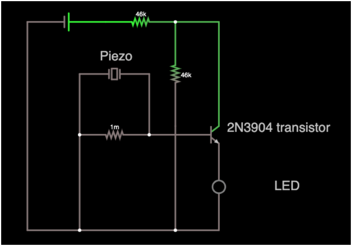
The two 47k resistors create a voltage divider. You can use any two resistors to form our voltage divider as long as they have the same value. E.g. 1m and 1m or 10k and 10k. They just need to be a pair (for our purposes).
Making it work
Once you have it wired up, tap directly on the Piezo, quite hard. If everything is wired correctly then the LED should flash as you tap. It’s pretty quick so you may need to be in a darker room. Check out this dodgy video on twitter.
What’s happening?
Let’s talk about a transistor. A transistor is basically an electronic switch or current amplifier.
In our case, we’re using it as a switch. When the voltage at the base (B) of the transistor is over a certain amount (in our case around 0.7 volts), the switch goes on. When the switch is on, current flows from the collector (C) towards the emitter (E) (the emitter has the small arrow on it - see the image below).
The maximum output voltage of our piezo when tapping is ~1.2 volts. So now, if you look at the circuit, can you see what’s happening?
When you tap hard enough, the voltage at the base exceeds 0.7 volts. This makes current flow from the collector to the emitter and from there through our LED.
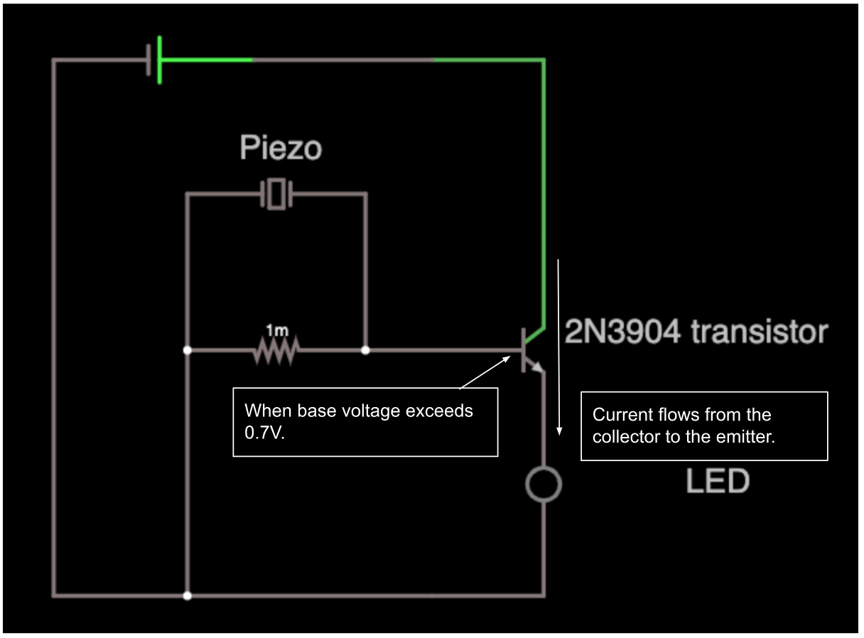
NOTE: the 1 meg resistor is called a “pull down” resistor. It makes sure the voltage at the base isn’t “floating” (which means to wander around potentially turning the transistor on) when the piezo isn’t connected. In our case it’s really not necessary, but if you hook this up and make it into a full drum pad, then you’ll want it.
Helpful hints
- Don’t worry if the above diagrams are confusing. This isn’t simple. Head over to the forum to ask questions and check out the many links. If you have a teacher at school in physics or computer science they may be able to help as well.
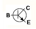
- Check the diagram of the transistor and make sure the pins are correct. Note the emitter E has the arrow pointing down in the diagram, and the base B is the wire in the middle of the transistor.
- The long pin of the LED needs connect to the emitter E of the transistor and the short leg goes to the -ve voltage.
Why is this cool?
This is a test circuit. It’s super useful because it tells you if your piezo drum pad is working, quickly and easily. That’s great because if build your own electronic drums, there are lots of things that can go wrong. This test circuit helps you know that the pads do work so you can focus your debugging efforts elsewhere.
Now, make the drum pad
Take the three parts from the lid of your set.

Glue the piezo to the middle of the aluminium sheet. I used super glue and it worked well.
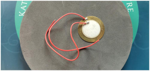
Using spray mount, glue the lighter foam directly over the piezo and the more dense foam on the other side.
IMPORTANT: Make sure the two wires remain accessible. Don’t glue them under the foam.
That’s it. Let it dry and you’re done with the pad.
You can try it again with your test circuit, but you’ll need to hit it with something like a chopstick.
If you’re stuck, take a look at these excellent instructions from Spikenzie. The instructions start 44 seconds into the video.
Making a full set of drums
Now you’ve built a drum pad you might want to build electronic drums. To do that, you need to buy an Arduino. They’re about $35. You can find instructions to build the drums on Instructables. They’re not the best and I will endeavour to write a better set as soon as possible.
https://www.instructables.com/id/MIDI-Arduino-Drums/ (uses Arduino and Garage band on Mac)
Good luck!
The Piezo
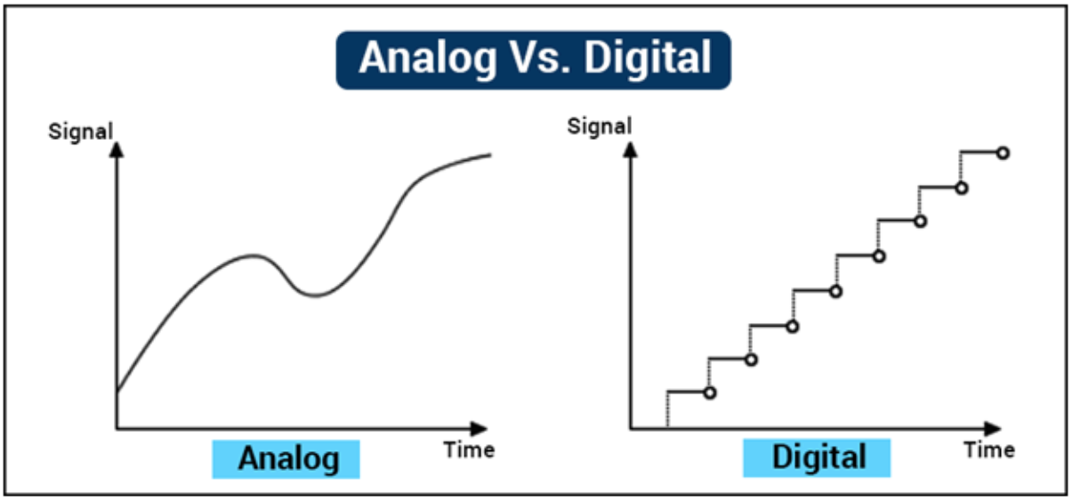
A piezo is an analogue sensor. It produces a continuous voltage related to how much it is being flexed or bent. Conversely, if you provide a voltage, it will vibrate (making it useful as a speaker for higher frequencies).
Check out youtube for an explanation of the difference between analogue and digital signals or have a look at the picture below.
