17, Electronics
Homemade lie or fear detector
(advanced experiment and you will need to purchase a 9v battery).
It’s worth reading all of these instructions in advance before you build this.
Introduction
How can we tell if someone is lying?
Well, one thing we know is that many people sweat slightly when they tell a lie. We can use this to build a simple lie detector.
Our bodies have a natural resistance to electricity. When we lie, the slight increase in sweat will decrease our body's resistance to electricity because sweat is a good conductor.
This is why lie detectors need to calibrated for each person. We need to find out how conductive the subject is when telling the truth and then measure the difference when they lie.
There are instruction in the link below to solder this project together (if you like the idea of soldering something)
However we’re going to make it using our breadboard. Breadboards are easier if you are new to making circuits since no soldering is required and it’s easy to correct mistakes. Pay attention however, it’s very easy to push wires into the wrong holes in breadboards and errors can be hard to spot.
Finding problems
If you make this and it’s not working, don’t get frustrated, that’s all part of learning. A great way to find the problem is to talk through each step with someone else. This is called pairing, and it’s a really great way to find problems. You can also pair while making this project which may help you avoid mistakes in the first place.
When I was testing this circuit, I made two mistakes, both around the variable resistor. It’s easy to do. I found them within a few minutes just by testing.
Will it work?
While fun to build this is unlikely to work to detect lies.
Why? Well for one thing, when testing yourself & friends, you’re not in a serious situation, and so you won’t start to sweat. The sweat reaction occurs when you’re truly stressed & in trouble, not pretending. Secondly, there’s huge variation across people. Some people don’t feel pressure as much as others and so don’t sweat much.
There is something that you can do to simulate lying, and that’s to make yourself scared. For example, I find my hands start to sweat when I watch free solo climbing. Watch Alex Harrno climbing without any ropes, and maybe your hands will sweat too.
When I built this circuit and tested it watching Alex free solo, the resistance definitely changed, but it wasn’t perfectly clear. Try it, you’ll hopefully see.
Then why do it?
This is a simple circuit for understanding how basic electronics and sensors work. A sensor similar to this could turn of your automatic watering system if it rains, or beep an alarm in bathroom if there was a water leak.
Let's do it
This is a basic circuit and as you’ll see a bit “twitchy”.
Step 1 - Things You'll Need You will need:
- Circuit board (a breadboard is easier - no soldering required)
- 10K resistor
- 47K resistor
- 470 resistor
- 1M resistor x2
- 47K VR (variable resistor)
- knob for VR
- 2N3904 transistor x3
- 0.1uf mylar cap (100nf)
- slide switch.
- 9V battery snap
- 9V battery (not included in set) or lemon battery
- LED (one red, one green)
- 2 x velcro strips (not il
- soldering tools (if soldering and not using the breadboard)
- drill
- basic tools
- tin
I found the best way to start is to layout all the parts you need on a sheet of paper, and clearly mark down the components. See the picture below.
You’ll need to work out your resistor values. Of course, I could have clearly labelled the resistors for you, but where’s the fun in that?
To find the correct resistors, install a resistor classifier app on your mobile, or use this online resistor colour calculator, then use your mobile camera to zoom in on the resistor so you can clearly see the bands of colour.
Note that yellow is often a lime green colour.
Finally, remember that it can be hard to tell which direction the colours are going on the resistor. Try both ways.
Step 2 - Finger pads
Make finger pads by wrapping aluminium foil around two velcro strips.
If you don’t have any velcro, use some cardboard and tape.
I simply took some foil and folded it (see the picture) then wrapped it around my fingers and taped it.
I’m sure you’ll come up with something!
Use an alligator clip to connect to the foil
The aluminium will conduct the electricity from the battery to a finger, around your hand and back to the detector through your other finger.
I found that it was better to put the pads on the same hand, but you should experiment.
Step 3: The Circuit (use a breadboard if you’re a beginner)
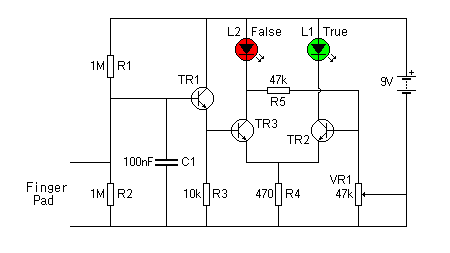
This may look a little complicated (actually it’s not once you can read the diagram but that can take a little time) and you will need to ask an adult or teacher with experience of basic circuits to help. Remember that doing this on a breadboard is easier if not quite as tidy because no soldering is required and you can easily correct mistakes.
Look at the picture below. Start at the top and work down, left to right.

R resistor TR transistor C capacitor L led VR variable resistor
If you're not sure what they look like, use google and look at images.
Place the red and green leds in, with the long led in the +ve power rail (which is marked with a plus).
Place the red lead from the 9v battery clip in the +ve power rail and the black lead in the -ve power rail.
Add in the 1M resistors (R1 & R2). One has a leg in the +ve power rail, and the other has one leg in the -ve power rail. Resistors are bi-directional, which means you don’t have to worry which way around you plug them.
Now lets add in a 0.1 uf (microfarad) capacitor. It will be marked 104 in tiny writing on the capacitor.
finally, let’s do the first transistor TR1. The collector and emitter of the transistor must sit across the central canal. Therefore you need to orient them at 45 degrees to the breadboard. This is where things start getting tight.
Don’t be afraid to use the entire board, and use connecting wires to join sections (as you can see I’m doing in the picture below).
Add the 10k resistor, R3 from the emitter of TR1 to the -ve power rail.
At this point take your phone and check all your connections. If things are getting too cramped, spread them out using connector cables. Remember, it’s easy for the legs of the resistors to touch and create short circuits if it’s too crowded.
Check that you definitely have the transistors oriented correctly. It’s easy to put them the wrong way.
If all is good, then let’s continue.
Add transistor TR2 with the collector in the same row as the -ve arm of the red LED.
Let’s now place the variable resistor in. It’s big and each leg needs to be in it’s own rail. See the picture. It has to align with the central canal and will need firm pressure to push it in.
Add the 470 ohm, R4 from TR2’s emitter to the -ve power rail. Then add in the 47k ohm R5 from TR2’s collector to the top of the 47k ohm variable resistor.
Then we need to put TR3 in place. The last part of our circuit. Notice that the -ve leg of the green diode DOES NOT intersect with R5 (see the little hop over the line from R5 to VR1, that means that the wires do not connect).
Finally connect your switch in the place. The switch isn’t shown in the circuit diagram. Can you think where it can go? Hint, you’ll need to adjust the battery connections.
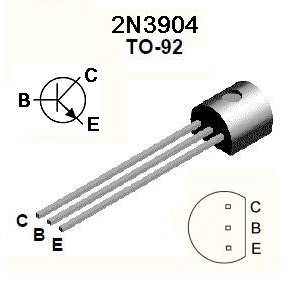
Note the orientation of the transistors.
 E = emitter
C = collector
B = base
transistors are super devices and at the heart of modern computers.
By tradition, the emitter points down with an arrow.
Did you work out the switch? You need to put it in series with either the positive or negative power (by convention the positive but either way works).
Your lie detector is ready to go.
First, wrap the finger pads around two separate fingers of the 'suspect'.
Then, slowly, turn the VR (the black knob on the outside) until the 'true' LED is light, and the 'false' LED is dark.
Then, question the suspect. When the false LED lights, the suspect is lying!
Neat hey?
Is this Pseudoscience? I.e. Does it work?
Well - maybe. People are different and some people don’t actually sweat enough when they lie to make this an effective instrument.
Modern lie detectors come in 2 flavours. The traditional polygraph uses a range of “biometric” measurements to try and tell if someone is lying which may include heart rate, blood pressure and other measured readings. Statistically they are supposed to be 80-90% accurate when used by a trained examiner. The new breed of systems are passive (you don’t need to be connected to them) and measure the individual’s vocalics, kinesics, eye gaze, facial features, and pupil dilation to assess credibility. They are around 60-70% effective.
Do you think they’re a good thing? If devices such as these are used in court, or for example airports (for asylum claims for example), what happens to a person when they’re wrong? 60-70% accuracy sounds good, but it means a false reading 1 in 3 times.
For this reason there is considerable debate about the efficacy of lie detectors. Read this wikipedia article which states that many scientists believe that the polygraph (another name for a lie detector) is “pseudoscience”, i.e. it’s something that is made to look like science but isn’t.
Pseudo science should be considered dangerous - and you should look for it. Anytime someone tells you something is true, but can’t back it up with independent research, first assume it’s false until you have verified it yourself. Be skeptical.